How I make my old Doorbell smart
ln my home office, I wear always my headphones. So I sometimes didn’t realize that my doorbell rings, and in time of the pandemic, I more working from home instead of from the office.
So I decided, to connect an ESP Device to my doorbell. This will trigger the esp up from its sleep and send me a small message to my Teams or Alexa or any other device that tells me “HEY THERE IS ANYONE AT THE DOOR!!!!”
My standard doorbell wiring is like this schematic design.
My problem is that I never thrust any IT design, so I need a backup. The Bell must be ringing, whatever happens. So the new architecture must follow this flow:
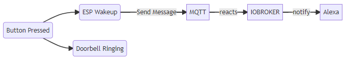
- Pushing the Button
- The Bell is ringing
- The Esp will wake up from its a deep sleep state
- The ESP will send a message to the MQTT Server
- IOBroker will react to the message and send a notification to e.g. Alexa
You will see, that the ESP Device will be attached to the doorbell as a secondary device.
Hardware setup
So I must separate the two circuits from each other. Because when the bell starts to ring, and the ESP will get the full power of the current transformer…it will be fried by the higher voltage.
So I must separate the two circuits. I decided to use an optocoupler to do this.
A (simple description) optocoupler contains internally a LED and a sensor. When the LED turns on, the sensor will recognize it. When the sensor indicates a light, it will close the second circuit, like a switch. When the LED turns off, it will interrupt the circuit.
The Internal LED of the optocoupler has a maximum voltage of 1.2 V. So I must attach a resistor before the optocoupler, to reduce the input voltage.
Components List
I ordered the following parts from my local seller
I Wiring it together according to this schema:

You will notice that the Doorbell will be attached through the device in a separate circuit. The main advantage of this wiring is the separation of the currency. On the left side of the optocoupler, the Transformator will be attached and on the left side, the ESP will be attached. So the ESP will be driven by a normal Lipo Battery with 3,7 Volt.
So when the user pushes the Ringing button, the circuit will be closed. Then the optocoupler will turn the internal led on. The sensor side of the optocoupler will be get closed to, and the esp will then get a signal.
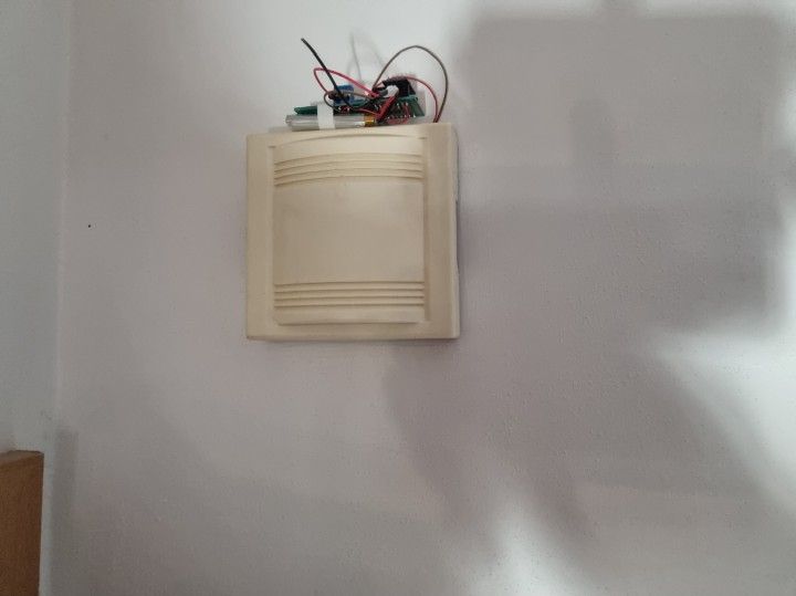
The final result will look like this:

Implementation
Instead of that, I describe every line of code, I will prefer to describe the schematic of the software specifics.
The Software itself can be found here on my Github repo.
So I want the longest runtime for this system, so my decision was easy. I must use the deep sleep mode of the ESP-Device. This sleep mode is there for maximum power saving, you can then wake the device up by a given of time, or you can attach the RST Pint with the Ground to wake the device up.
When the device wakes up, it will execute the code in the setuproutine of the code. The loop will not be recognized in this mode. After the setup was executed, you must set the device in deep sleep by yourself withESP.deepSleep(0) . This tells the device to go in deep sleep mode.
Within the setup routine, you can do anything you like. I will open up a connection to the MQTT broker and send then a message to it.
These messages will be recognized by my home automation (iobroker). That will turn on my desk lamp with a blink effect (driven wled).
Together with this, I use a Pushsafer service to get a notification on my mobile phone too. So when I am not at home I will get notified of a delivery guy was there or another person was ringing.
Conclusion
Sure you can buy an Amazon ring or s.th. but my problem with this was, that the ring consume more power than I was willing to give. So I thought about another “easier” solution. That the origin bell let be ringing, and the new smart home one let acting too. This project was the result of it.
That’s all folks. Let me know if this article what you think about it. Also, comments are welcome too. You will find this project also at my GitHub project too:
 SBajonczak